Preliminary Documentation of a Hunting Skiff
at Beaufort Maritime Museum’s Boat Storage

Noah Edwards
Alyssa Saldivar
Trenton Zylstra
Dr. Lynn Harris
HIST 6881- History and Archaeology of Small Watercraft
i
Table of Contents
List of Figures………………………………………………………………………………………….iii
Basic History and Notes……………………………………………………………………………1
Digital Inking…………………………………………………………………………………………..3
Hand Inking…………………………………………………………………………………………….5
Pencil Drawn Measurements……………………………………………………………………7
Original Sketches…………………………………………………………………………………….9
Measurement Proformas…………………………………………………………………………12
Photos………………………………………………………………………………………………..….17
ii
List of Figures
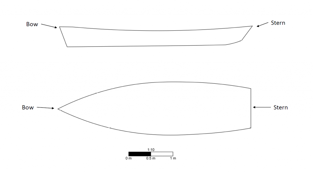
Figure 1. To scale digital inking of plan and profile view with labels………………………….….3
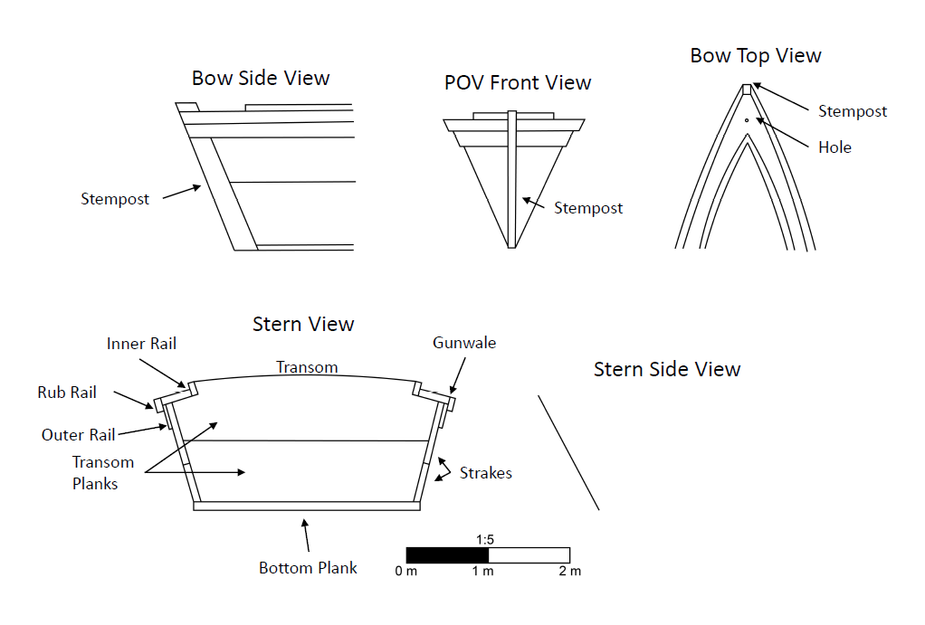
Figure 2. To scale digital inking of transom and bow views with labels………………………….4
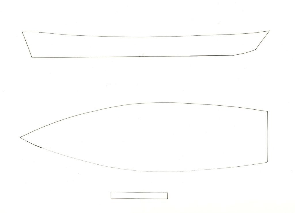
Figure 3. To scale hand inking of plan and profile views………………………………………….……5
Figure 4. To scale hand inking of transom and bow views…………………………………………….6
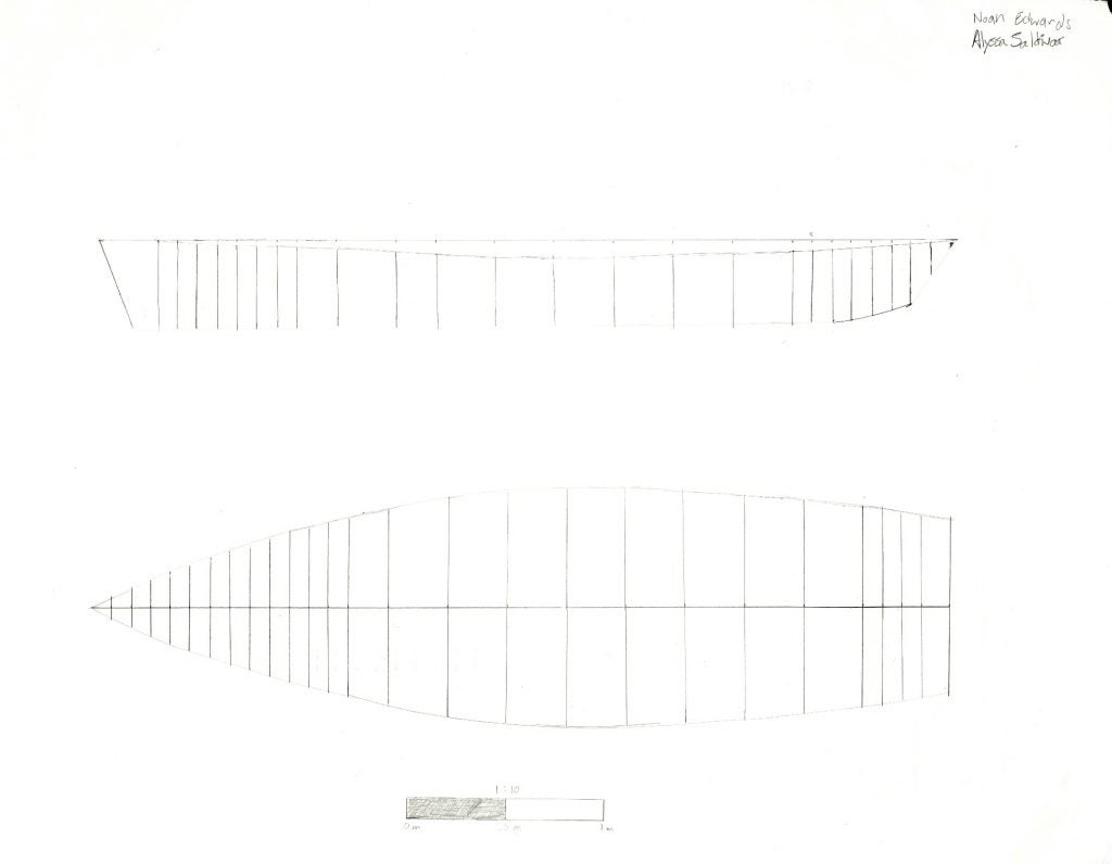
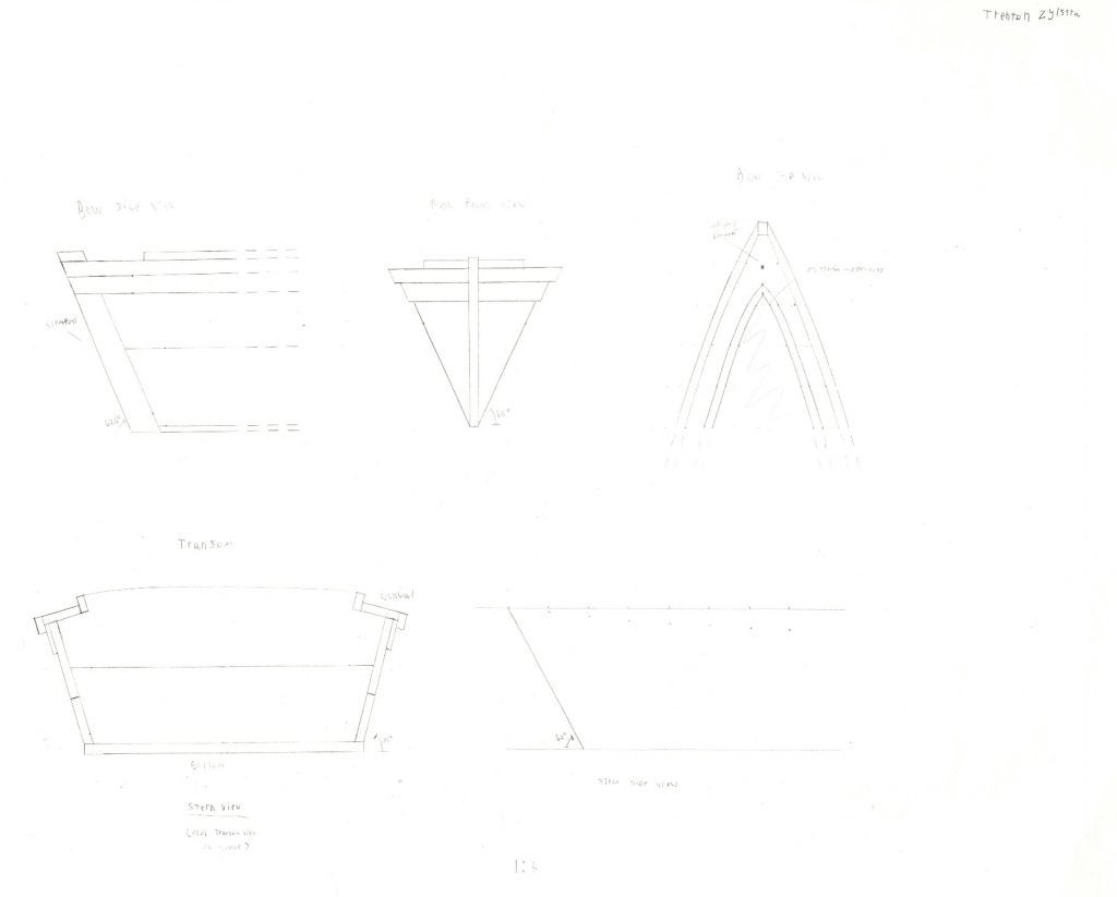
Figure 5. To scale pencil drawing of plan and profile views……………………………………..……7
Figure 6. To scale pencil drawing of transom and bow views………………………………….…….8
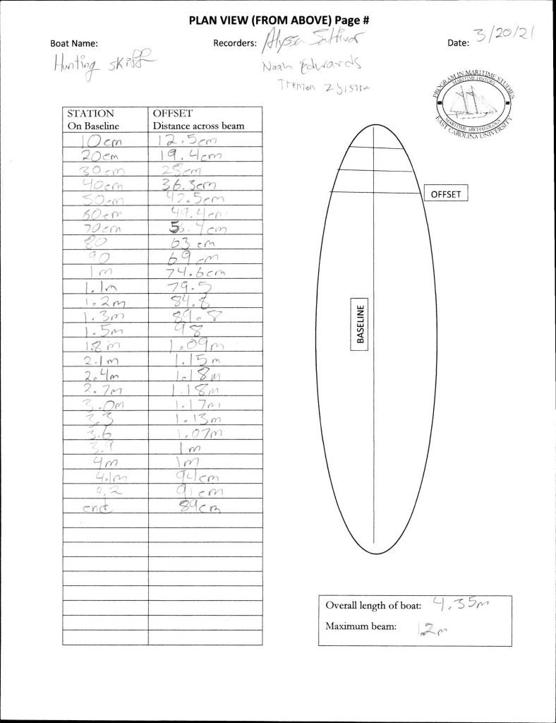
Figure 7. Plan view sketch with labels…………………………………………………………………..…….9
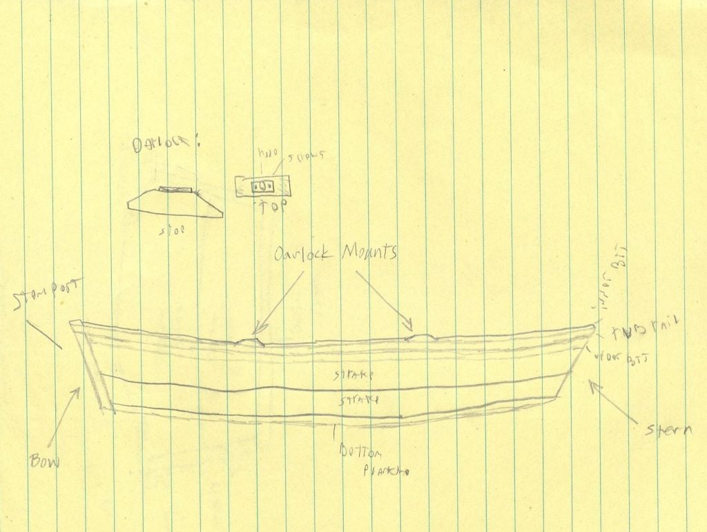
Figure 8. Profile view sketch with labels………………………………………………………………..…..10
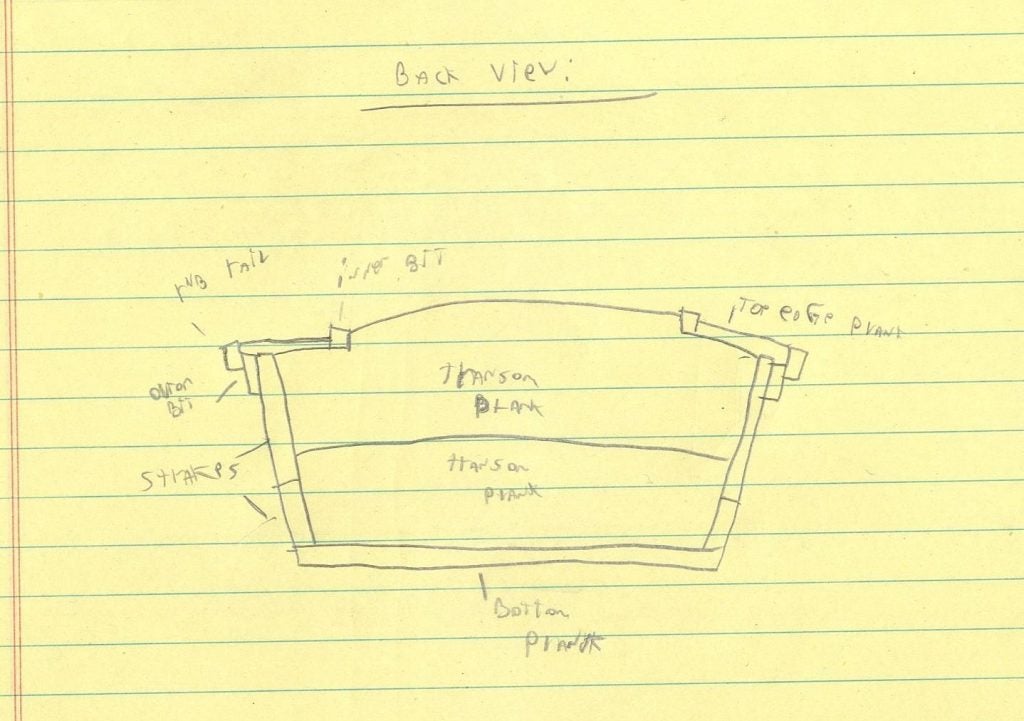
Figure 9. Transom view sketch with labels…………………………………………………………….……11
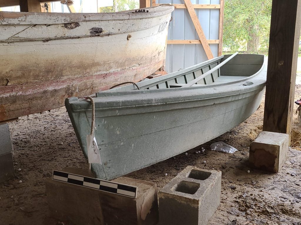
Figure 10. Bow photograph………………………………………………………………………………………..17
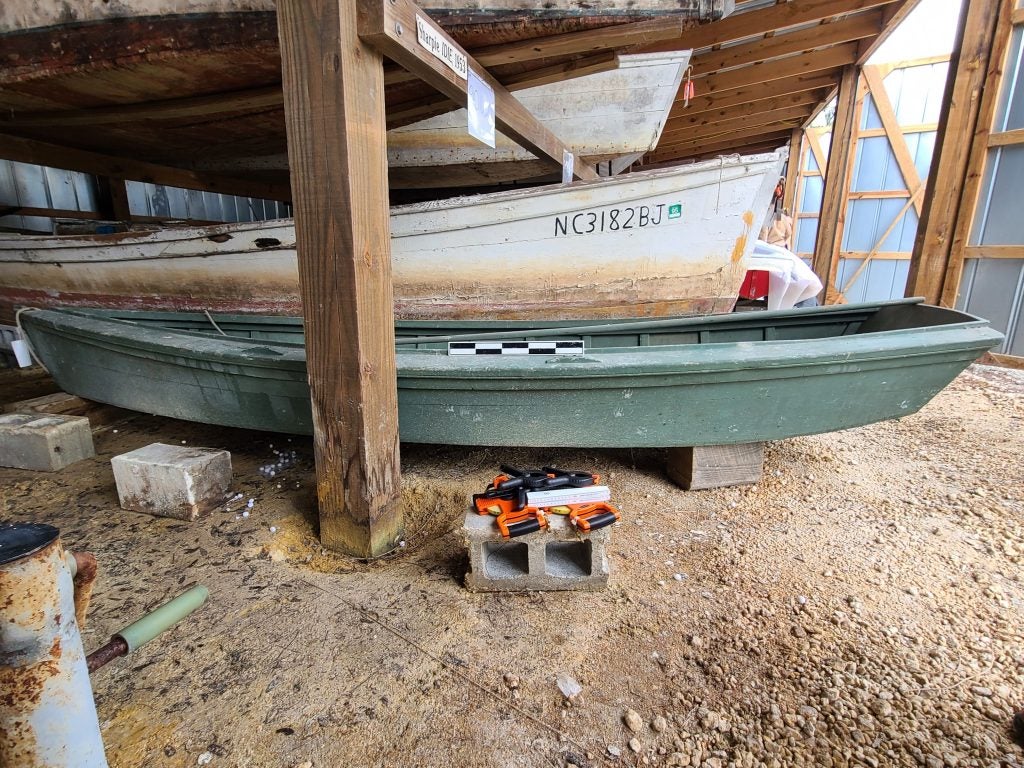
Figure 11. Profile photograph…………………………………………………………………………………..…17
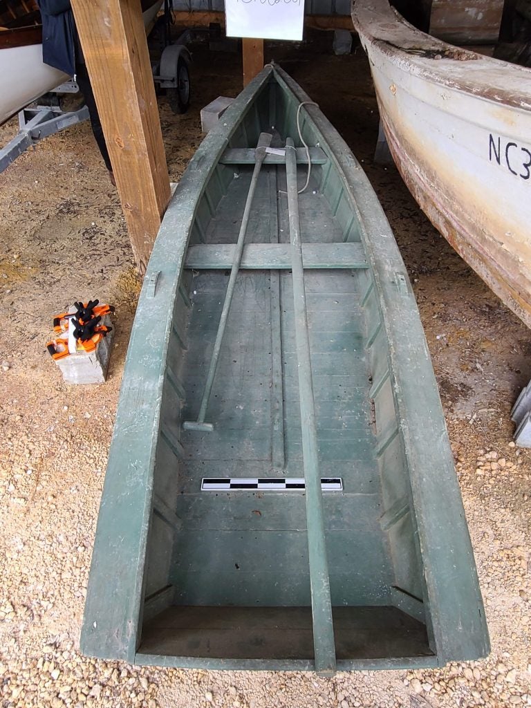
Figure 12. Plan photograph……………………………………………………………………………………..…18
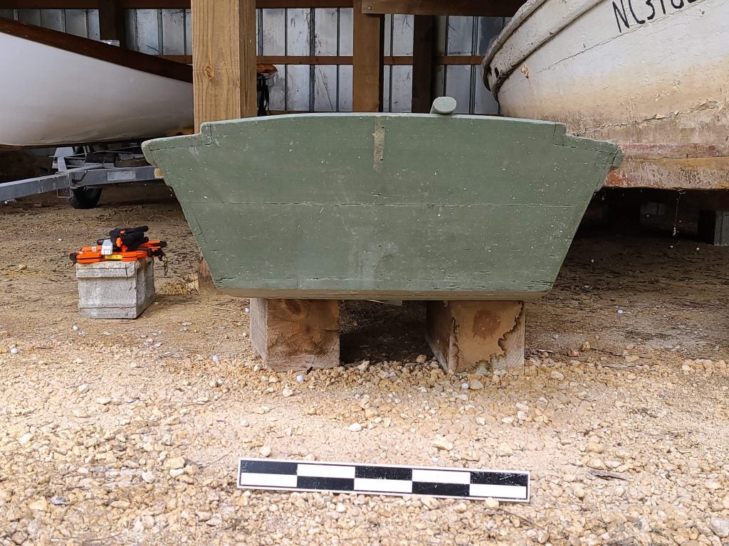
Figure 13. Transom photograph………………………………………………………………………………….19
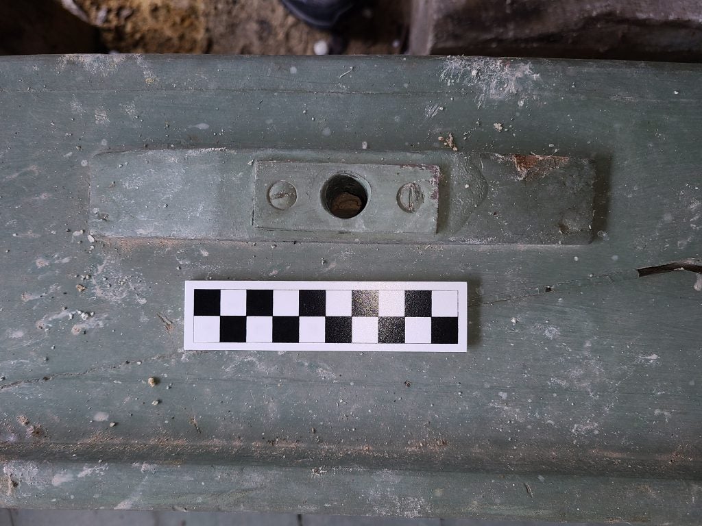
Figure 14. Oar lock photograph…………………………………………………………………………….…….19
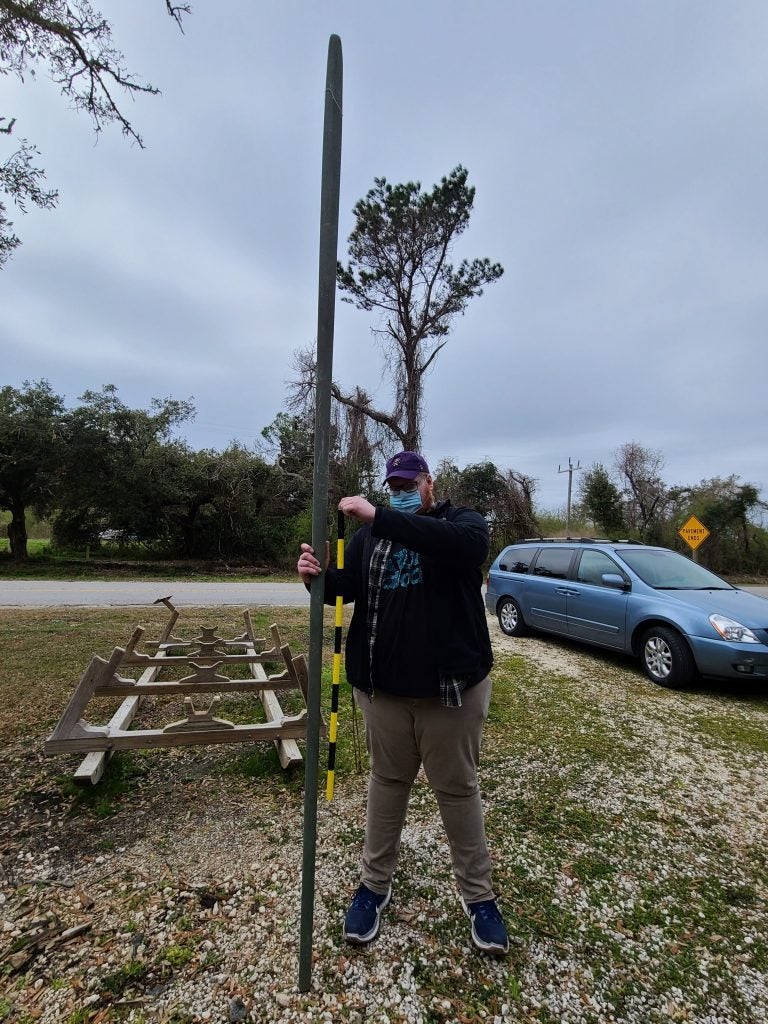
Figure 15. Pole photograph…………………………………………………………………………………………20
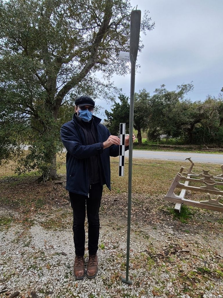
Figure 16. Sweeper photograph. …………………………………………………………………………..……21
iii
Trenton Zylstra
Notes Taken:
20 March 2021
Hunting Skiff
Boat style from 1870 to 1960s
This one likely built in 1940s
For hunting with guns
Hull:
Flat bottom
Hard chine
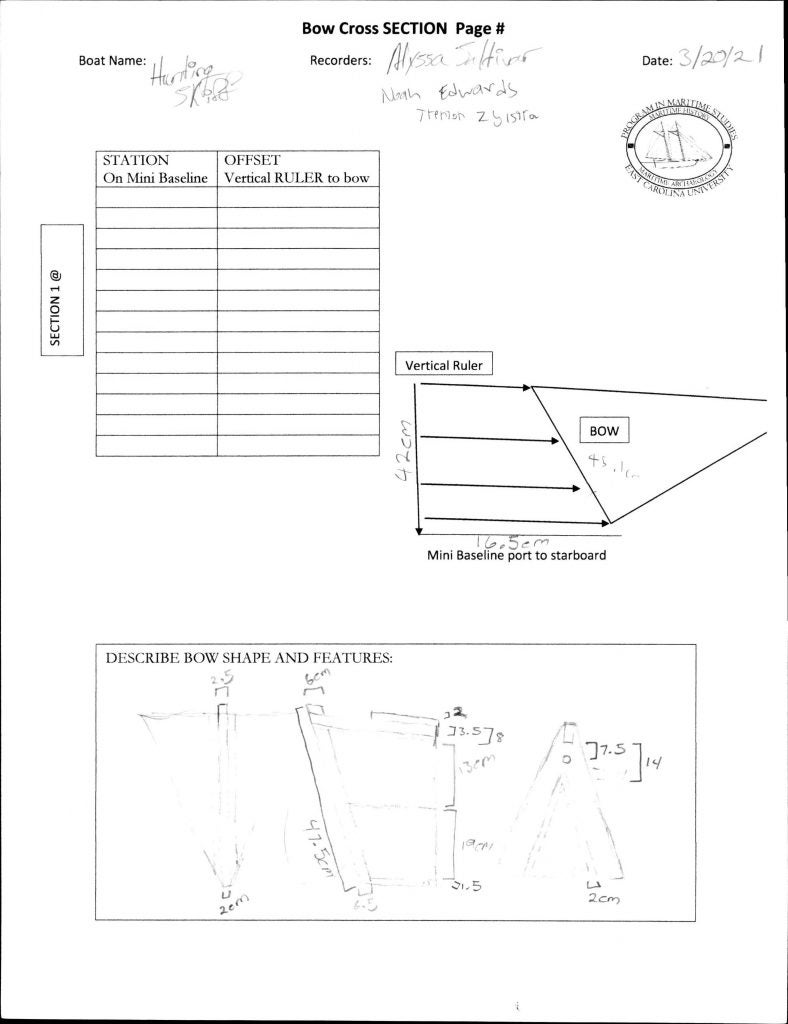
Bow pointed
Stern flat
Hull sides curve out slightly from transom then curves in more sharply into triangle bow
Most curve back in happens in from ½
Bottom planking
27 lateral planks
Shape of bottom flat except where it curves up in the back until it meets the transom
Curve mostly between frames 11-13
Plank reinforcing bottom
Transverse along the center of the boat
Starts on top of plank 6 and goes until is on top of plank 24
Side Strakes
2 transverse per side
curved
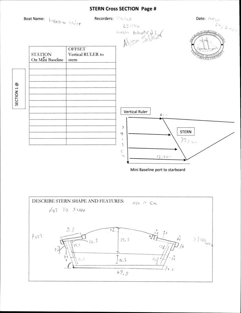
Transom
2 lateral planks
13 Frames
Straight up and down
Stern frame in corner and angled
Only on the strakes, do not extend onto floor
Equally spaced
Beveled edges
Gunwale
One flat plank with rim on inside and outside and plank underneath on outside that rim overlaps Gunwales each make of 2 strakes with a diagonal scarf (port side angled: / )
1
Benches
One at ¼ front One at ½ middle
Both benches supported by crosspieces underneath positioned between 2 frames
Front bench is between frames 3 and 4 (counted from front)
Middle bench is between frames 7 to 8
Beveled edges
Stempost emerges through gunwale slightly
Inner rims of gunwale meet in a triangle at bow
Hole between stempost and inner rim of gunwale through which a line goes
Has line through hole
Stempost raked forward
Transom
Transom raked outward
Flat
2 lateral strakes
Oarlocks, only mounts no pins
2 on each side
Two above frames 5
Two above frames 9
Offset toward the bow
Trapezoidal shape
Rectangular metal cover on top with hole, a screw on each side holds them in
Oars missing
Condition
Good
Painted green with some scuffing
A few cracks but not compromising
Punt
Oval shaft
Extra long blade
Longer than the other
Estimated 10 feet
Sweep for steering
Circular shaft, tapering
Small, rounded, cylinder crosspiece at top
Shorter blade
Estimated 7 feet
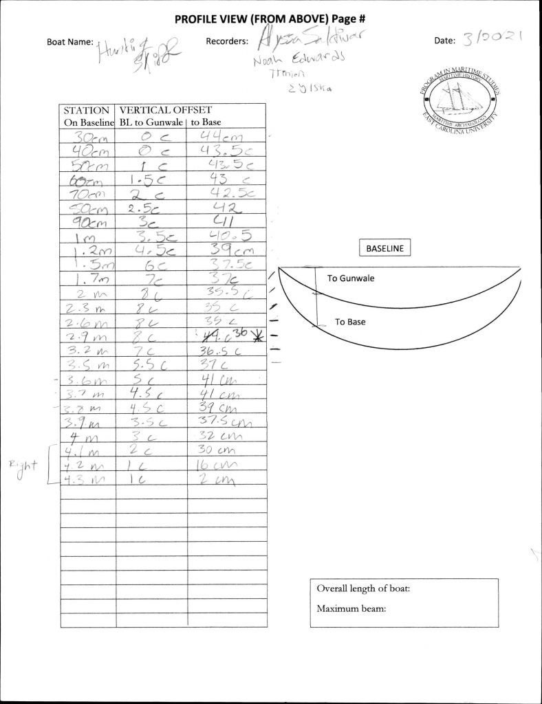
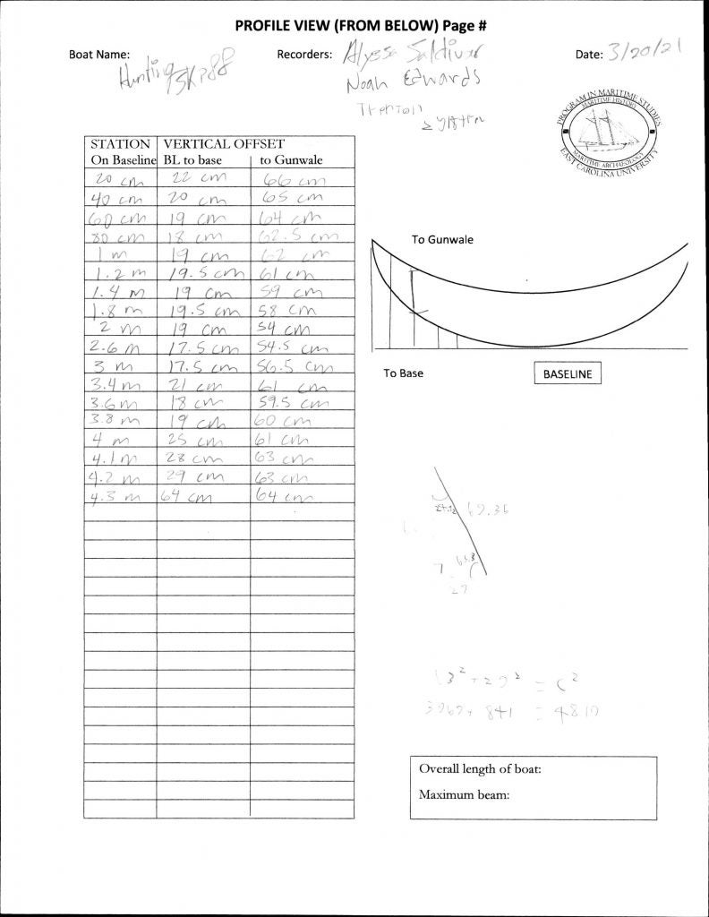
Notes on the measurements taken 20 March 2021
As the team was only given a day to measure this vessel, some measurements will need to be revised in the future. The rise of the stern and the angle at which the gunnels meet in the bow will need to be readdressed. The profile view of the vessels will also need to be remeasured as some of the measurements did not align properly towards the transom.
2
3
4
5

6
7
8
9
10
11
12
13
14
15
16
17
18
19
20
21